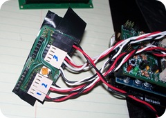
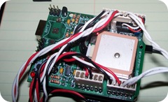
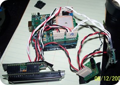
After two evenings (late into the night) of soldering and de-soldering and re-soldering, I have the hardware side of the project pretty much complete.
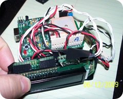
Here’s the entire setup; in this shot I had everything pushed in tightly to get an idea of the final size. You can see the electrical tape on the back of some of the boards to prevent shorts.
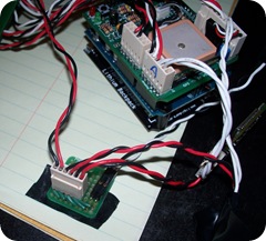
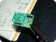 Instead of tactile switches, I chose to use a silicone button that resembles a TV remote. Here the PCB half of the buttons is mounted on a 1" (2.5 cm) square ProtoBoard along with a header that provides power, ground, and a return to the two button pins. I built the pull down resistor circuits on the board under the button PCB.
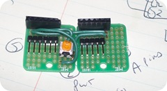
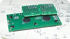
Two more of the little boards make up the breakout board for the LCD. I thought that I had ordered a larger board to build this on, but must have missed it. Luckily I had ordered a few extra of these just to have around. They are nice little boards; each group of 3 holes has a trace between them. Wiring up small breakouts like this is a breeze since everything is through hole, and there are no other connections on the back.
The trim pot for the LCD contrast is on this board as well. This is one part of the design that will probably change at some point. It is a pain to adjust since it is behind the LCD. Depending upon how easy it is to see the LCD outside, I may even have to put a full size pot (or a linear one) somewhere.
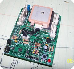 I removed the original headers from the GPS Logger Shield, and replaced them with polarized connectors. I figured that this would make maintenance and hookup easier. Ultimately I would like to have projects that are contained on shields or custom boards, but since I’m not sure what the end result of finding or building an enclosure will be, I decide to go with connectors for this one.
Since the unit can be powered from USB or battery, and since the battery will charge when the Arduino is plugged in, I built a small power distribution board to make sure that everything that needed power got it.
The Arduino’s 5v and ground are running to the LCD which in turn is forwarded to the power board. The battery plugs directly into the power board, and then feeds the Bluetooth and buttons.
Below are a few shots of the various cable runs. I really should get some more wire, in different colors, but they only had 3 colors at Sparkfun!
Connectors to the LCD, and power board.
Everything plugged in up top. Notice the new jumper for the GPS. I didn’t want to hard wire anything at this point. The white wires running to the right go to the buttons and Bluetooth.
Everything hooked up!
At this point there is still one more wire to hook up: I forgot to do the battery monitor wire.
I still have some software issues to tackle, but I think I’m going to get it bolted to something first. I’m planning to take the entire unit for a short hike on Saturday, so I’ll get to test it out.

